| Author | Message | ||
| Luigi Nicoletti (2mmuch)
Junior Member Username: 2mmuch Post Number: 64 Registered: 9-2002 |
Hello again. Just want to close the issue that I had with the bad running 87TR. James said that all car need was a good adjustment so I brought my car in for my emissions test and it failed. The shop I brought it to had a gas analyzer and he adjusted everything to bring it back to Ferrari standards and made it pass. After I got the car back it has been running great ever since. What a difference a well tuned Ferrari makes. Thanks You Everyone | ||
| Steve Magnusson (91tr)
Intermediate Member Username: 91tr Post Number: 1663 Registered: 1-2001 |
Agggh!!! -- Well, it won't hurt to have the idle microswitch stuff working properly. Since you've verified that most of the input signals to the injection ECUs are OK, you'll have to start looking at the output side of things so first a little background: 1. Each injection ECU only supplies one output signal which is a signal to their respective Electromagnetic Pressure Actuator (or sometimes called the Electo-Hydraulic Actuator -- "EHA units" as mentioned previously by Brian K. in this thread). The EHA is a solenoid coil device hooked up to pin 10 and pin 12 on the injection ECUs. 2. When cold (i.e., large NTC sensor resistance) and just after start-up, the injection ECU puts a relatively large current (on the order of 100~200 mA) thru the EHA to enrich the mixture (open-loop mode). 3. As the injection ECU detects things heating up (i.e., the NTC sensor resitance decreasing) and as time passes from start-up, the current to the EHA from the injection ECU is reduced to a lower level (on the order of ~10 mA) to lean things out (still open-loop mode). 4. Eventually Relay A opens (when the hot/cold thermoswitch opens) and the injection ECUs (detecting no ground signal from Relay A) then modulate the low current levels flowing thru the EHAs based on the voltage signal they gets from their respective O2 sensor trying to keep the O2 sensor output ~0.5V avg (closed-loop mode). Ideally, what you'd like to do is measure the current flowing from pin 10 thru the EHA to pin 12 (or the voltage from pin 10 to pin 12 assuming the EHA resistance is reasonable) in the various open-loop and closed-loop modes to see if anything looks wacky, but this is a major b*tch since when the connectors are fully-plugged in you can't probe them with the voltmeter (fortunately for me, I've never had to do this). If you need to go there, my guess is that it would be easier to cobble something up at the EHA connector side rather than the injection ECU connector side (perhaps on the EHA side you could partially unplug the connector enough to leave it electrically connected to the EHA but expose the contacts enough to make a voltage measurement across the two terminals). I'm also a little surprised that you report good cold-running with the injection ECUs unplugged since I would've guessed that this would lean out the mixture too much (but maybe the mechanical mixture tweaks are set to the rich side of things to compensate so it quasi-works unplugged when cold). Before resorting to the functional EHA voltage measurements, it wouldn't hurt to unplug the injection ECUs and measure the DC resistance in the connector from pin 10 to pin 12 (which will be measuring the electrical resistance of the EHA) just to see if they're similar/reasonable. Also, if you have good cold-running with both the injection ECUs unplugged, but bad cold-running with them both plugged in, you might try plugging them in one at a time to see if one is "good" and one is "bad" -- if so, you could then swap the injection ECUs, repeat the one-at-a-time test, and see if the problem follows the "bad" injection ECU or if it stays with same "bad" connector position -- just some thoughts... | ||
| Luigi Nicoletti (2mmuch)
Junior Member Username: 2mmuch Post Number: 53 Registered: 9-2002 |
Steve I adjusted the microswitch and now get 12.6V to 13.8V I kept the voltmeter on the terminals and moved the microswitch slightly until it clicked and the meter went over 12V. But there was no change with the idle going up and down. But after I put everthing together I went and started it one more time to make sure it started, and what do you know it was running great. I noticed one thing I forgot to plug in the injection ECUs. I turned the car off and pluged them back in and tried it again. The idle went back up and down???? | ||
| Steve Magnusson (91tr)
Intermediate Member Username: 91tr Post Number: 1661 Registered: 1-2001 |
I used a 9/32" (6-point) nut driver to adjust mine (and it was a little tight-ish) so they must be nominally 7mm hex, but maybe the plating is a little thick and/or they're just made outside the high side tolerance. Relay A only clicks "on" once when cold and then clicks "off" when the hot/cold water thermoswitch opens, but Relay E will click if the intake manifold vacuum drops suddenly when in the cold mode (i.e., if you open the throttle plates a little quickly). If you're measuring the brown/white wires on Relay D terminal 86 and don't get +12V at idle (hot or cold) you've got a problem regardless of what relay is or isn't clicking so as long as you're measuring the brown/white wires directly that's the best place to look IMO. | ||
| Luigi Nicoletti (2mmuch)
Junior Member Username: 2mmuch Post Number: 52 Registered: 9-2002 |
Steve Checked the D relay one more time on pin 86 and it shows .11 this time. Didn't have much time to check because we hit an outside high of 82degs today so the car wasn't that cold to start. We are expecting some colder weather this weekend so I can try again then. The relay did click a couple of times. Could the clicking be from relay "A"? Went to adjust the microswitch but it seems that the nuts are to small for an 8mm socket and to big for a 7mm socket is there such a thing as a 7.5mm wrench? | ||
| Steve Magnusson (91tr)
Intermediate Member Username: 91tr Post Number: 1656 Registered: 1-2001 |
Lou -- You lost me a little. As you said, the #1 thru #4 results all look OKish, but on #5 if Relay D pin 86 (two brown/white wires) never goes +12V, I don't see how you "can hear the relay click on and off" (i.e., if Relay D pin 86 never goes +12V then Relay D will not go "on" and should just always stay "off")? You can loosen the two bolts holding the idle microswitch and rotate its housing slightly (relative to the throttle body) to see if you can get Relay D pin 86 to go +12V at idle (when engine running). It's really kind of a flaky arrangement since you don't want the idle microswitch internals to prevent the throttle plate assy from closing properly against it's idle adjustment setscrew, but at the same time you want the contacts inside the idle microswitch to just close at idle too. If trying the adjustment doesn't get it to work then you should probably remove the idle microswitch and make the direct resistance measurements shown in the TR WSM (pin 2 should connect to pin 18 at idle and pin 3 should connect to pin 18 at WOT) just to confirm the gizmo is fritzed before replacing -- but I still want to understand "I can only get .08v and I can hear the relay click on and off"... | ||
| Henryk (Henryk)
Member Username: Henryk Post Number: 644 Registered: 8-2001 |
Luigi: Keep the posts coming. I am very interested in what you find.....with Steve's help. I recall, last year, that my 88TR had a similar, but thankfully very intermittent problem....but when trying to restart after the car was already warm.....not cold. The car would start, then the idle would go down to zero, and car would quite running. I had to feather the throttle to keep it running. Sometimes it would work, after a while, and sometimes not. During these times I found it best to turn off the ignition, and start the car again. Eventually it would run fine. I wonder if this would be a related problem to yours. | ||
| Luigi Nicoletti (2mmuch)
Junior Member Username: 2mmuch Post Number: 51 Registered: 9-2002 |
Steve Did all the tests and these are the results. 1 Water thermoswitch cold goes from 11v � 14v as car idle goes up and down. Water thermoswitch hot goes to .01v on terminal 87a and 85. 2 Oil thermoswitch cold goes from 11v � 14v as car idle goes up and down. 3 Relay A 87b reads .08v - .11v signal to the injection ECUs 4 Ground Check Relay D pin 85 = .08 Relay A pin 30 = .08 Relay A pin 86 = .08 5 Throttle microswitch I can only get .08v and I can hear the relay click on and off. After all of these test it looks to me I have a problem with the throttle microswitch. What do you think. Thanks | ||
| michael marchese (Bigdog)
Junior Member Username: Bigdog Post Number: 82 Registered: 8-2001 |
Steve Maybe I should have the shop (FOD) do that while it's there? It started doing this rather abruptly but infrequently. | ||
| Steve Magnusson (91tr)
Intermediate Member Username: 91tr Post Number: 1649 Registered: 1-2001 |
michael m. -- I'd be glad to stop by and commiserate, but I don't have the tech resources/background for a 308 2-valve K-Jet. There will be a series of electrical events when cold vs hot that it usually takes the descriptive text in the OM, WSM, and a wiring diagram to figure out -- if you want to do the homework, I'd be glad to consult. If those check out, then you'd need to measure the various pressures -- supply, control/cold, control/hot (I've got a K/KE-Jet fuel pressure gauge/adapter set so let me know if you want to borrow it). If those check out, then you should be able to tweak it up if it's still got a runability problem. The ultimate diagnostic end game is to measure the actual fuel volume discharge from each injector vs airflow plate deflection (and I've not yet been, nor want to go, there -- although I bought the graduated cylinders  ). ). | ||
| michael marchese (Bigdog)
Junior Member Username: Bigdog Post Number: 77 Registered: 8-2001 |
Lou, I read your response on my post about my 308 cold start up problem. I replaced my fast idle valve or air bleed valve and it may have solved my problem, not sure because it's at the shop with unrelated problems they caused (that's another story) but hopefully this fixed it. Also the info Steve Magnusson is providing is one of the best on the site and way better than my limited knowledge. Hey Steve I live in Westminster would you mind coming over to take a look at my 308 and see what you think? | ||
| Steve Magnusson (91tr)
Intermediate Member Username: 91tr Post Number: 1644 Registered: 1-2001 |
OK Lou -- Are you ready for this? First, the names for the relays you'll be probing are: Relay "A" is the 0 332 015 006 relay Relay "D" is the 0 332 204 101 relay I'm not sure that the wire colors inside the black box 100% match the wire colors in the harnesses so confirm by the relay terminal numbers. If necessary, unplug the relays and each terminal should be marked/indicated somehow. I'll give these to you in a sort of order to follow (as the engine warms up from cold to hot). This is with everything plugged in: #1. Checking hot/cold water thermoswitch cold mode Start engine cold (water less than 36 deg C) Measure voltage on Relay D terminal 87a (one orange/black wire)-- should be +12V when coolant has gone below 36 deg C to close thermoswitch (and stay +12V until coolant is warmer than 63 deg C to open thermoswitch). #2. Check oil thermoswitch If the oil temp has not gone below about 5 deg C or is above 15 deg C the oil thermoswitch should be also be closed. Measure voltage on Relay A pin 85 (one orange/red wire) -- should be also be +12V when the Relay D terminal 87a is at +12V unless the oil is very cold. #3. Check Relay A is sending the "I'm cold and running my air pump" ground signal to the injection ECUs. When you verify Relay A pin 85 is at +12V in step #2 above (water cold, oil not too cold), measure the voltage on Relay A pin 87b (two violet wires) -- should be a good ground (e.g., well less than 0.4V) #4. Check system ground (this can be done hot or cold) Measure any of: Relay D pin 85 (two black wires) Relay A pin 30 (two black wires) Relay A pin 86 (two black wires) should be a good ground (e.g., well less than 0.4V). #5. Confirm throttle microswitch operation (this can be done hot or cold): Measure voltage on Relay D pin 86 (two brown/white wires) -- should be +12V at idle and near ground when the throttle plates are opened. Alternatively (if the D relay itself is still OK), you should be able to feel/hear the D relay click "on" when at the idle position and click "off" when you slightly open the throttle. #6 By now you could go back to #1 and verify that Relay D terminal 87a goes to near ground when the water temp gets up to about 63 deg and the hot/cold thermoswitch opens (Relay A terminal 85 will follow Relay D terminal 87a and will also be groundish when the hot/cold thermoswitch opens). The ball is in your court ... | ||
| Luigi Nicoletti (2mmuch)
New member Username: 2mmuch Post Number: 50 Registered: 9-2002 |
Steve Opened up the box and I have version #3 with 5 relays just like you discribed. | ||
| Steve Magnusson (91tr)
Intermediate Member Username: 91tr Post Number: 1643 Registered: 1-2001 |
Lou -- the triangular black box has the two round connectors (C12 and C13) on it (there are three boxes under the TR RH fender -- the first two are the injection ECUs, the rearmost is the black relay box). | ||
| Luigi Nicoletti (2mmuch)
New member Username: 2mmuch Post Number: 49 Registered: 9-2002 |
Steve I guess where going in. I assume the triangular black box is one of the box's I check the ecu connectors on, they're both under the RH rear fender so I can't quit see what shape they are. | ||
| Steve Magnusson (91tr)
Intermediate Member Username: 91tr Post Number: 1642 Registered: 1-2001 |
Their locations are shown in both the OM and the WSM: hot/cold water thermoswitch -- On the LH side of the same aluminum housing that has the coolant NTC sensor. It's a SPST switch that should be closed cold (less than 36 deg C) and open hot (greater than 63 deg C) with (engine running) one red input wire that's always +12V and one orange/black output wire that should be +12V cold and near 0V hot). throttle microswitch -- On the outboard (RH) side of RH thottle body (the shaft of the throttle microswitch is connected to the end of the RH throttle plate shaft). {But I still think it's better to make functional voltage measurements inside the triangular black box since this tests the component and more of the interconnections/wiring than just checking the component itself -- JMO.} | ||
| Luigi Nicoletti (2mmuch)
New member Username: 2mmuch Post Number: 48 Registered: 9-2002 |
Steve Where is the hot/cold mode thermoswitch, and the throttle microswitch located. Thanks | ||
| Steve Magnusson (91tr)
Intermediate Member Username: 91tr Post Number: 1641 Registered: 1-2001 |
Lou -- There are three general electrical things that could be checked (engine running) by probing around the relay connections inside the triangular black box (with a little disassembly): 1. Do the injection ECUs have a good ground connection, 2. Is the hot/cold mode thermoswitch working, and 3. Is the throttle microswitch closing at idle, but I'd need to know your black box relay configuration as mentioned in the earlier message to identify which KE system and the proper/easiest place to measure on the relays. If you want to proceed let me know... | ||
| Luigi Nicoletti (2mmuch)
New member Username: 2mmuch Post Number: 46 Registered: 9-2002 |
Ok I just changed the coolant NTC sensor and there is no differance. I just want to state again this is whats happening. When I start the car cold and I keep my foot on the gas it runs fine, As soon as I let my foot of the gas the rpm's drop an the car's idle goes up and down and somtimes even stall. It used to rev about 1500 rpm's then drop as the car got warmer. Once the car warms up it runs great. I just notice another thead on F-chat with the same problem. Called "Cold Startup **help**. | ||
| Steve Magnusson (91tr)
Intermediate Member Username: 91tr Post Number: 1617 Registered: 1-2001 |
Sounds like a good strategy Lou... | ||
| Luigi Nicoletti (2mmuch)
New member Username: 2mmuch Post Number: 43 Registered: 9-2002 |
Steve I'm going to try what Brian suggested before I start getting into all the electrical stuff. Once I locate the NTC Sencer and see how it works I might just replace it and see what happens. I'll post what I find later this week. Thanks | ||
| Luigi Nicoletti (2mmuch)
New member Username: 2mmuch Post Number: 42 Registered: 9-2002 |
Henry I found the section for the air valve in my WSM and see that the valve is only opened alittle and closed all the way when warm. Thats what mine look like. I thought it was had to be opened alot more then that when cold. I can safly say that it checks out fine. Thanks. | ||
| Steve Magnusson (91tr)
Intermediate Member Username: 91tr Post Number: 1615 Registered: 1-2001 |
Lou -- It will be shown in the TR OM in a Figure in the injection section IIRC (it's in the thermostat housing area toward the front upper area of the engine) -- or someone please post the SPC illustration if you've got it handy. There are two independent NTC devices built into the single NTC sensor (each is hooked to pin 21 on their corresponding injection ECU). There's also a similar-looking thermoswitch sensor in the same area (whose function we'll check if we ever go inside the black box), but the connections are different enough to tell them apart. Order it on-line at www.importeccatalog.com for $22.85 (but $40 is not a horrible retail price IMO). | ||
| Luigi Nicoletti (2mmuch)
New member Username: 2mmuch Post Number: 41 Registered: 9-2002 |
Thanks Henry I'll try that tonight. Steve or Brian would it be posible to show me where this coolant NTC sensor is located. It sounds like there is two of them. I found a Bosch dealer in town and gave him that number he wants $40.00US each. | ||
| Henryk (Henryk)
Member Username: Henryk Post Number: 621 Registered: 8-2001 |
Lou: I re-checked the WSM and the air valves are open when cold, and closed when warm. Quote: "When engine is cold section 4 is open and allows additional air into the intake chamber increasing the idle speed....when warm....closes the air duct". This is found on page D16 of the WSM. While not impossible, I would find it unusual that BOTH valves are bad at the same time. Place the valve in the freezer for a while, and re-chek to see if it is open. Then heat them to make sure they close. | ||
| Luigi Nicoletti (2mmuch)
New member Username: 2mmuch Post Number: 40 Registered: 9-2002 |
Henry Just checked the auxiliary air-valves and they are both closed when my car is cold. At first you said they should be closed, but then you came back and said the should be opened when cold. If this is true then my air-valves aren't working? | ||
| Steve Magnusson (91tr)
Intermediate Member Username: 91tr Post Number: 1614 Registered: 1-2001 |
Lou -- Got your note saying that you've got the 16 metal terminals in the injection ecu connectors, but now I'm unsure that even that is enough to identify your system with certainty (i.e., the different KE systems could use the same harness and just not use some of the lines). I've found three different schematics for TR KE so you're going to have to actually look inside the triangular black box and check the number and type of relays inside -- if we need to go there (I'll describe that below). Brian K.'s suggestion to replace the coolant NTC sensor (Bosch PN 0 280 130 032 -- don't pay more than $22.85) is a good one and could be done with no regrets IMO. (Although it was not my ultimate gremlin,) mine had aged to ~8.5K ohms at 3 deg C on both sides; whereas, the new replacement was ~5.6K ohms at 3 deg C on each side. If you want to measure yours, unplug the injection ecu connectors and measure the resistance from pin 21 in each connector to a ground on the engine: 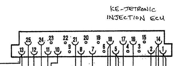 Use this chart from the WSM to check your results at the particular coolant temp of your measurement: 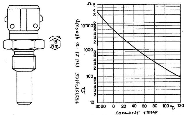 To dig deeper on the electric side, you'll need to remove/open the triangular black box. There are (at least) three possibilities on what's inside: Possibility #1 KE with 3 relays in the black box (KE standard version) 1 each oddball relay with a fuse 1 each 0 332 204 101 relay 1 each 0 332 014 113 relay Possibility #2 KE with 3 relays in the black box (TR WSM) 1 each oddball relay with a fuse 2 each 0 332 014 113 relays Possibility #3 KE with 5 relays in the black box (US TR wiring diagram) 1 each oddball relay with a fuse 1 each 2nd oddball relay 1 each 0 332 204 101 relay 1 each 0 332 014 113 relay 1 each 0 332 015 006 relay Let me know if you want to go there and tell me which of the three configurations above match you car. | ||
| James J. McGee (Dr_ferrari)
Junior Member Username: Dr_ferrari Post Number: 69 Registered: 7-2002 |
Luigi, Sounds to me like the engine is in need of a good adjustment of the mixture and balance of the banks. on the TR, If it is off balance, the engine will run exactly as you describe. Call your local tech and have the throttle plates adjusted and balanced, and the idle and mixture set to specs. that should solve your problem. Best regards, and good luck. Jim | ||
| Brian Keegan (4redude)
Junior Member Username: 4redude Post Number: 93 Registered: 7-2002 |
Out of the million things to check, the EHA units (black plastic part on the side of the fuel distributor) and the water temp sender for the fuel injection which is shown as item #19/Tav.12 in the 1987 TR parts book. I have sold these parts to frustrated customers who replaced everything else prior to that trying to narrow down the problem. | ||
| Steve Magnusson (91tr)
Intermediate Member Username: 91tr Post Number: 1602 Registered: 1-2001 |
. | ||
| Steve Magnusson (91tr)
Intermediate Member Username: 91tr Post Number: 1601 Registered: 1-2001 |
New idea for identification -- unplug one of the connectors on one of the injection ECUs. It's a 25 position connector, but not every position will have a metal terminal. As I read the schematics: A "KE with O2 sensors" system will have 16 metal terminals A "KE without O2 sensors" system will have 12 metal terminals -- let me know your count... (And it probably wouldn't hurt to unplug/reseat both injection ECU connectors as well as the two round connectors on the black box.) | ||
| Luigi Nicoletti (2mmuch)
New member Username: 2mmuch Post Number: 39 Registered: 9-2002 |
I only see a sensor right in the middle of the cat. body. with 2 wires coming out of each. | ||
| Steve Magnusson (91tr)
Intermediate Member Username: 91tr Post Number: 1600 Registered: 1-2001 |
Lou -- I want to be sure I asked the question correctly -- do you have: 1. an O2 sensor at each cat inlet and a thermocouple sensor at each cat outlet or 2. just a thermocouple sensor at each cat outlet? | ||
| Luigi Nicoletti (2mmuch)
New member Username: 2mmuch Post Number: 38 Registered: 9-2002 |
Steve Yes there is a sensor on each Cat. | ||
| Steve Magnusson (91tr)
Intermediate Member Username: 91tr Post Number: 1599 Registered: 1-2001 |
Lou -- I was afraid you'd say that (if it's KE and it runs/idles OK warm -- it now becomes a cold-mode electrical gremlin hunt)! More questions: 1. Are there O2 sensors at the cat inlets? (KE came both ways on TRs - KE with O2 sensors and KE without O2 sensors)? 2. Have you tried unplugging/cleaning/reseating the round connectors on the triangular black box under the RH rear fender on top of the wheel liner? The real hassle is the way every electrical connector in the injection systems is designed it's virtually impossible to measure anything without the special "testbox" shown in the WSM. If you remove and open the triangular black box you can get to some of the terminals on the various relays inside for measurement -- but I'd like to know which KE version you have before we go "hunting" there. | ||
| Henryk (Henryk)
Member Username: Henryk Post Number: 615 Registered: 8-2001 |
Lou: To check the air valves, make sure that they are both "open" when cold, and "closed" when warm. In a previous response I told you the reverse. | ||
| Luigi Nicoletti (2mmuch)
New member Username: 2mmuch Post Number: 37 Registered: 9-2002 |
I don't have the regulators in my car so I will remove the auxillary air-valve to see if they are working ok. | ||
| Henryk (Henryk)
Member Username: Henryk Post Number: 613 Registered: 8-2001 |
Lou: One can see the warm-up regulators, in the top photo, and they are gone in the bottom one. They are right inside the nearest intake runner in the picture. Steve: Thanks for the correction. I was familiar with my US model TR.....which does not have the warm-up regulators. | ||
| Luigi Nicoletti (2mmuch)
New member Username: 2mmuch Post Number: 36 Registered: 9-2002 |
mine looks like the KE picture. | ||
| Steve Magnusson (91tr)
Intermediate Member Username: 91tr Post Number: 1598 Registered: 1-2001 |
Lou -- "Euro" doesn't describe which injection system you have (e.g., a Swiss TR will have KE-Jetronic while a GB TR will have K-Jetronic). The jpegs below show K-Jetronic (which has gizmos under the intake plenums) and KE Jetronic (which doesn't): K-Jetronic 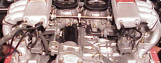 KE-Jetronic 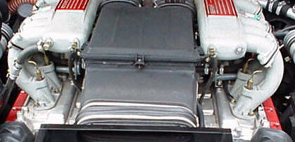 Does your's look like either of these systems, or is it different still? | ||
| Henryk (Henryk)
Member Username: Henryk Post Number: 612 Registered: 8-2001 |
I was thinking of possibly something wrong with the air injection system, which works at cold idle. It sounds like you have an air leak somewhere........causing the RPMs to vary. There are no warm-up regulators on the TR. The TR has a KE-Jetronic fuel management system; whereas the warm-up regulator was in the K-Jetronic system.......as in the Boxer engine. A common problem is the auxillary air-valve. There are two of these....one for each bank. They function only when cold. One could be open when cold......should be closed.......These can be removed and checked just by looking. Good luck.........it really can be a million things!!!!!!!! | ||
| Luigi Nicoletti (2mmuch)
New member Username: 2mmuch Post Number: 35 Registered: 9-2002 |
It's an 87TR, it's the Euro model and yes all the emmissions are intact. | ||
| Henryk (Henryk)
Member Username: Henryk Post Number: 611 Registered: 8-2001 |
What is the year of the car? US model? Are the emmissions intact? | ||
| Luigi Nicoletti (2mmuch)
New member Username: 2mmuch Post Number: 34 Registered: 9-2002 |
My TR when its cold ideals real bad. It sounds like I'm tapping the gas pedal and the ideal revs up and down. Once the car is warm it runs great. I�ve talked to several people and was told it could be a million things. Vacuum leak, Warm-up regulator (which I can�t find on my car), Thermal time switch, etc, etc. So I thought I would turn once again to the guys who live and breath F-Cars. It just doesn�t look good when your getting out of a party with your wife and your sitting in the car for about 10 minutes waiting for the car to warm up. Heck that�s a long time sitting with your wife,  and hearing about how we should have taken the other car, �we would be home by know�. Looking for any suggestions? and hearing about how we should have taken the other car, �we would be home by know�. Looking for any suggestions? Thanks |