| Author | Message | ||
| Patrick S. Perry (Psp1)
Junior Member Username: Psp1 Post Number: 159 Registered: 3-2001 |
I'd love to have a copy of the schematic as well. Anyone reverse engineered the ignition coils with the circuitry for a TR? I have heard that production has stopped and they are "OMG" expensive for a coil and a small circuit. | ||
| Rob Schermerhorn (Rexrcr)
Member Username: Rexrcr Post Number: 762 Registered: 11-2002 |
This is correct even today. The reason is exhaust emissions. My suggestion is to read through the Bosch Electronic and Electrical Systems available here. Rob Ps, great idea! | ||
| DGS (Dgs)
Junior Member Username: Dgs Post Number: 238 Registered: 5-2003 |
"A richer engine is safer to drive and lasts longer." Not when the carbon builds up. The lambda set system runs rich when cold and at WOT, when you need the richer mix. The Lambda loop returns it to the "proper" mixture, as determined from the O2 sensor. | ||
| Bill White (Nc_newbie)
Junior Member Username: Nc_newbie Post Number: 151 Registered: 2-2003 |
So what you are telling me is basically the car runs leaner in closed loop than open loop (i.e. 5.3-6.3V open vs. 6.4-7.4 closed). If this is the case then I'll take the 0.5 mpg drop in fuel economy to have the extra power. A richer engine is safer to drive and lasts longer. That is probably why they ground it at idle and WOT. Sounds to me like a gimick to save gas at mid throttle with no real benefit (except to run the engine lean which in not good for it) at mid (i.e. highway)...and to pass us emmissions... (which I can do at idle with flying colors) thanks to idle mixture adjustment. Back to the subect though... I can add this circuit to the ecu if necessary. I probably will but add a switch to turn it off if this is the net result but would like to understand it a little better. I will do some measurments with this control wire grounded. I have noticed though my car feels like it has more power with the ecu disconnected (which this would explain)... | ||
| DGS (Dgs)
Junior Member Username: Dgs Post Number: 236 Registered: 5-2003 |
The light connects at pin 2, with an "RM" (red striped brown) wire. According to SB 80-29, the open loop conditions on an F105C040 (US) engine are: 60% duty cycle (7.4 +/- 0.2 VAC across FV) when cold, 50% duty cycle (6.4VAC +/- 0.2), water <57c,> 25C, 60% duty cycle (7.4VAC) at WOT. Closed loop (5.3-6.3VAC) with coolant > 59C, oil > 25C, cat > 300C Since the throttle microswitch is grounded at the extremes and open at mid-throttle, I'd guess that the control output to the Lambda computer is grounded until the cat reaches 300C to keep the car in open loop until the cat warms up. As far as I can tell, this is the idle side of the throttle switch (with the oil temp sensor parallel to the WOT side). But SB 80-29 (testing of the lambda computer) doesn't mention the car being forced into open loop at idle. Alas, reverse engineering would probably require measuring a functional cat ECU -- if anyone can find such a thing.  | ||
| Bill White (Nc_newbie)
Junior Member Username: Nc_newbie Post Number: 150 Registered: 2-2003 |
Ok we are talking about the same wire. I said Orange w/yellow but technically I guess it is pink/yellow. I talked to a number of Ferrari people about this and they all say that this is an output only. Not an input for entering open/closed loop and the only feedback/impact of this circuit is the light on the dash. However, my car feels lean if the light is on. I can put a scope on my freq valve but I need a more details on duty cycle to tell the diff in open versus closed loop to see if grounding this pin actually make a difference. What is the duty cycle in open vs closed loop and how do I make it change in each mode? Bill | ||
| DGS (Dgs)
Junior Member Username: Dgs Post Number: 235 Registered: 5-2003 |
It's pin 4. The 328's wiring diagram doesn't show the colors at the connector, but it's marked "SG" (pink striped yellow) once it leaves the ECU board. From the wiring diagram, I can't really tell whether the lead is grounded or a voltage source, and what it's value is supposed to be above or below 300C. It feeds directly into the Lambda computer (pin 6) and through a diode to the idle position of the throttle microswitch going to the Marelli ignition computer (pin 19). I'm guessing that it's ground below 300C, to emulate "idle" condition (at the Lambda computer) until the cat warms up. Because of the diode, the Marelli should still detect idle normally. You can check for a closed lambda loop by checking the duty cycle at the frequency valve. If it varies, it's in closed loop. | ||
| Bill White (Nc_newbie)
Junior Member Username: Nc_newbie Post Number: 149 Registered: 2-2003 |
My car is a mondial 3.2 should be the same as the 328. I would like to investigate this "control" wire. Do you have a color for it. It could only be the orange with yellow trace ( white or yellow) on the ECU. When I reverse engineered this thing I could not find that circuit. It is possible I should Ground the "control" wire at 300 degrees. That would be easy to do by wiring in the second comparator to OC pull down transistor. How can I check to see if my car runs open or closed lambda loop based on the state of this control wire. I know the orange/yellow goes to the throttle micro switch and to the ECU. That may also explain why the car feels lean if the slowdown light is on (i.e. this function not working correctly on the cat ECU)? However if this signal is grounded by the ECU then it seems the self test function would not work properly when the cat is hot unless it is also timed to not pull the control wire until some period after the car is started. Thanks for the interest... | ||
| DGS (Dgs)
Junior Member Username: Dgs Post Number: 233 Registered: 5-2003 |
Ah, which model is this for? According to the specs on the 328, that cat ECU has one control (ground) lead that switches at 300C to enable the lambda loop, flashes the light at 900C, and turns the light on steady at 940C. | ||
| Bill White (Nc_newbie)
Junior Member Username: Nc_newbie Post Number: 148 Registered: 2-2003 |
I haven't done one electronically yet. It is rather simple. Four wires (Power, GND, light, and Running). You Gnd the light to turn it on (OC). The running light only has 12v on it when the car is running. Therefore the circuit has only two sections. A one-shot that is on for 3 seconds triggered by the running wire. The second section has two sets of resistors in series (with the cat thermocouple) being one of them. They are input to a 339 comparator. This way you can set the value (temp) to transistion the comparator. The output to both sections go to transistors connected in a wired-or to pull down the light wire if either section is active. Bill | ||
| DGS (Dgs)
Junior Member Username: Dgs Post Number: 231 Registered: 5-2003 |
I'd be interested in seeing the schematic, if you have it electronically. Ever consider doing up a printed circuit? | ||
| Bill White (Nc_newbie)
Junior Member Username: Nc_newbie Post Number: 147 Registered: 2-2003 |
After having a new cat ecu intermittenly flash on after just a month I got irritated and designed a better one. This one will never go out. If any else needs one let me know and I could build one for you for my time or send you the schematics. Also mine you can adjust at what cat temp you want the light to come on.  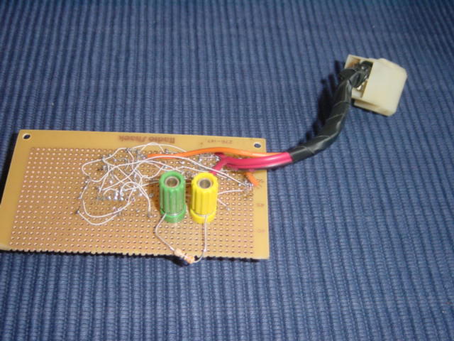 |