| Author | Message | ||
| Oldslow308 (Djparks)
Member Username: Djparks Post Number: 503 Registered: 2-2003 |
'Top Secret Thingamajig" | ||
| '75 308 GT4 (Peter)
Advanced Member Username: Peter Post Number: 3014 Registered: 12-2000 |
So I was correct, it is a thingamajig!  | ||
| Oldslow308 (Djparks)
Member Username: Djparks Post Number: 501 Registered: 2-2003 |
Peter, Thanks on the lights. As I was was telling some of your Canadian brothers at the last show,.............secret government stuff, I'd have to kill you if I told you! Really! It's a camera so I can get the license numbers of everybody that cuts me off in traffic. Actually, it's a remote mounted radar detector head. It mostly picks up electric eyes at 7-11's and supermarkets. Makes for a good conversation piece. Maybe we should start a new thread, "Name That Box". DJ | ||
| '75 308 GT4 (Peter)
Advanced Member Username: Peter Post Number: 3008 Registered: 12-2000 |
Damn, that looks great DJ! I don't know if you mentioned it to me before (if at all), but what's that thingamajig above your front licence plate? | ||
| Steven R. Rochlin (Enjoythemusic)
Member Username: Enjoythemusic Post Number: 656 Registered: 4-2002 |
Lovely! Great job... and many of us owe a big thanks to Ferrari U.K.! Enjoy the Drive, Steven R. Rochlin | ||
| Oldslow308 (Djparks)
Member Username: Djparks Post Number: 498 Registered: 2-2003 |
Complete with European lenses courtesy of Jeff and Mark at Ferrari UK.  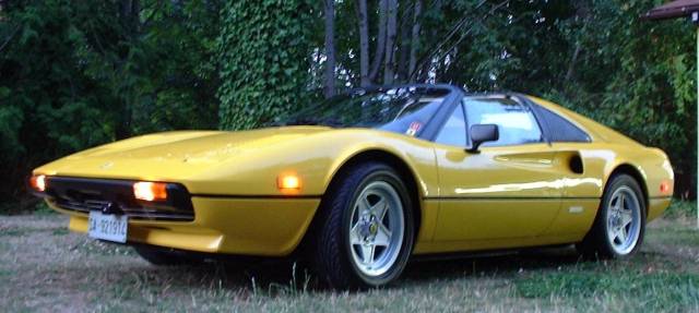  | ||
| Oldslow308 (Djparks)
Member Username: Djparks Post Number: 477 Registered: 2-2003 |
HA! | ||
| Hans E. Hansen (4re_gt4)
Intermediate Member Username: 4re_gt4 Post Number: 1647 Registered: 4-2002 |
Err, forget what? | ||
| Oldslow308 (Djparks)
Member Username: Djparks Post Number: 472 Registered: 2-2003 |
Closer than you think! Thats why I am asking about them now before I forget! | ||
| Hans E. Hansen (4re_gt4)
Intermediate Member Username: 4re_gt4 Post Number: 1642 Registered: 4-2002 |
Si, senor. It should click. I suspect it doesn't, unless the lever is moved very slowly, as you did experimentally. So, when you become a senior citizen, perhaps the capacitors should be added. <g> | ||
| Oldslow308 (Djparks)
Member Username: Djparks Post Number: 470 Registered: 2-2003 |
Hans, along those same thoughts, if indeed the relay cycled during movement of the light stalk from high to low and back it would click would it not? I definately did not hear it until I moved the lever SLOWLY. You may have a point there. | ||
| Hans E. Hansen (4re_gt4)
Intermediate Member Username: 4re_gt4 Post Number: 1641 Registered: 4-2002 |
Whilst in the shower, this thought came to me. (When you have as much area to wash as I do, you have a lot of spare time to think.) Inductors (coils of wire) store energy in a manner that can be sort-of compared to capacitors. Because of this, there is a small time between disconnecting the power, and the relay actually releasing. This time delay *may* be more than the small transcient experienced when moving the light switch. In other words, the relay may not actually cycle when high/low beam is switched. This would render the need for a capacitor moot. | ||
| Jonathan (Birdman)
Junior Member Username: Birdman Post Number: 122 Registered: 6-2003 |
Oh Boy, now I have to dig out EE101 and remember it!! First, here's the circuit I'm proposing...  I'm using the good old: V(t)=Vi(e^-t/RC) equation for capacitor decay and making the assumption that we don't want the voltage to drop more than 10% (hence V(t)/Vi=.9) over the interval of .1 second and assuming for now 50 ohm coil resistance. This simplifies down to : C=-t/[(ln(.9)R] (someone check my algebra!) If t=.1 sec and R=50 ohm, then I get 19,000 microfarads (THATS a big ass capacitor) which is why I suggest a current limiting resistor. Someone please check my math and if anyone has the solenoid handy, get a reading of the coil resistance. If the coil resistance is higher, the cap can be smaller. Jonathan | ||
| Jonathan (Birdman)
Junior Member Username: Birdman Post Number: 121 Registered: 6-2003 |
RE: Capacitor... I wouldn't just throw a cap in there. When you turn on the lights, there will be a huge surge of current as the cap charges (Because you'll need a fairly large capacitance to work in this function). The surge may be enough to pop one of the diodes or even the fuse. My suggestion would be to also add a 5 ohm resistor in series (1 watt). This would limit the surge of current when the cap charges but wouldn't drop the voltage too much that the solenoid won't work. (This is an old tube amp trick!) If someone would be so kind as to measure the DC resistance of the coil on the solenoid, I will determine how much capacitance is necessary and post a schematic. Best, Jonathan | ||
| Hans E. Hansen (4re_gt4)
Intermediate Member Username: 4re_gt4 Post Number: 1638 Registered: 4-2002 |
I suppose the equation: t = RC would suffice. So, if you desire "t" to be, say, 1/10 sec, and assume the relay coil resistance (I'm assuming that is what this circuit powers) is perhaps 50 ohms (total guess), then you'd need .1 = 50C or 2000 uF. (Other issues here, such as the inductance of the coil, etc., but for this simple circuit, we can probably ignor all the complications.) | ||
| Oldslow308 (Djparks)
Member Username: Djparks Post Number: 465 Registered: 2-2003 |
Can anyone venture to guess what size and type to use? It would be really easy to add to the circuit and would perfect the modification. DJ | ||
| Hans E. Hansen (4re_gt4)
Intermediate Member Username: 4re_gt4 Post Number: 1636 Registered: 4-2002 |
Yeah, yeah! Capacitor! Despite what others are saying, I agree that there is probably a small 'glitch' in transitioning from low to high beam. Might not be noticeable, but I'm sure it's there. | ||
| Jonathan (Birdman)
Junior Member Username: Birdman Post Number: 118 Registered: 6-2003 |
Hi Verell, You are right...sorry I was confusing the TOP (input side) of the fuse box with the bottom (output side). On the input side, there are multiple tabs that are bus-barred together with nothing but rivets making the connection and I can assure you they fail because that was the source of an annoying electrical failure in my car. I soldered them and they gave no more trouble. However, even if the rivet on the bottom isn't the only connection, the two tabs on the output side of the box are only in direct contact, not soldered, so there is a chance that corrosion could cause a problem there. I stick by my assertion that the high current load (headlights) should be on the front connector and the low current load (bucket lifting solenoid) on the rear. I made up my little diode wire doodad today and I'll install it when I get the car back with the new clutch! COOOL stuff. Now if we were really clever, we could put a capacitor from the solenoid trigger to ground to hold a charge for a tiny bit of time, making sure that the buckets don't move when you change from HI to LOW beams. OK, maybe that's going a little too far.... David, I know what you mean about it being an induced problem....you have to TRY to make the buckets move by switching the lights from Hi to Low very slowly. Nonetheless, there is a tiny glitch in the power to the headlight lifter motors no matter how fast you move it (unless you can move it faster than the speed that the solenoid can switch!) Just because the motors don't have time to move does not mean that they didn't get a very fast signal telling them to move. I'm just wondering (not taking sides...just wondering) if over several years, this might prematurely wear out the motors. Probably not, but worth at least pondering. Jonathan | ||
| Oldslow308 (Djparks)
Member Username: Djparks Post Number: 464 Registered: 2-2003 |
Hans, You may be right. I haven't had a 4 headlight car for a long time but I seem to recall the beam shifting in the low beam light when the brights were used. Back to plan A I guess.......... | ||
| Oldslow308 (Djparks)
Member Username: Djparks Post Number: 463 Registered: 2-2003 |
Hans, By all logic your assumptions would be correct. One wire only from a low beam circuit to the low amp 'signal' input on the motor relay and you're done! (you would still have to maintain the high amp power supply to the other input terminal of the motor relay though) Go for it! As far as the 'dipping phenomena' Dave is correct. With normal operation of the light stalk the buckets remained stationary. I induced the dipping by 'messing around' to see if it could actually happen. Second only to installing 16" wheels on my car this is one of the best upgrades I've done to this thing. DJ | ||
| Hans E. Hansen (4re_gt4)
Intermediate Member Username: 4re_gt4 Post Number: 1634 Registered: 4-2002 |
Wait, late breaking news. I probably mis-spoke (mis-typed??). The low beam light has 3 terminals, so there is a different filiment in the bulb when in high beam use. So the low and high beam circuits are indeed separate, and, thus, the diodes ARE needed. Or so I think. Maybe. Perhaps. A definite 'could be'. | ||
| Hans E. Hansen (4re_gt4)
Intermediate Member Username: 4re_gt4 Post Number: 1633 Registered: 4-2002 |
I probably didn't word it well, Dave. What I was getting at was that there is no possibility of a transition, induced or otherwise, if the circuit was powered entirely off of the low beam light on a GT4. It stays on all the time. This *should* (I think) eliminate the need for the diodes, as their function is to allow motor power to come from either the high or low beam circuits (because the low beam circuit is 'off' when using high beam. No?). On the GT4, you should be able to power from the low beam only, as it's on all the time. Hans. (just call me 4-eyes) | ||
| Jerry W. (Tork1966)
Member Username: Tork1966 Post Number: 861 Registered: 7-2001 |
Just did mine a couple of weeks ago...I love it!! | ||
| dave handa (Davehanda)
Intermediate Member Username: Davehanda Post Number: 1529 Registered: 5-2001 |
Hans, Just so people don't get the wrong idea; the "temporary dipping phenomenon" as you are calling it, is an "induced" problem. In other words one you have to create, it will not happen in normal use. So is is not really a problem; and if it occurs, hurts nothing. | ||
| Hans E. Hansen (4re_gt4)
Intermediate Member Username: 4re_gt4 Post Number: 1632 Registered: 4-2002 |
Peter and company: I'm thinking that the GT4 doesn't need the diodes, as there is 4 headlights, and the low beams stay on all the time. This also should eliminate the "temporary dipping phenonenon" described a few posts below. Comments? | ||
| Oldslow308 (Djparks)
Member Username: Djparks Post Number: 462 Registered: 2-2003 |
My pleasure Peter, so when are you going to start on yours? DJ | ||
| '75 308 GT4 (Peter)
Advanced Member Username: Peter Post Number: 2983 Registered: 12-2000 |
I'm jealous of you GTB/S guys, your boxes have relatively easy access to, compared to the GT4's (tucked into the bottom corner of the glove box). Thanks for the procedure DJ, it makes a little more sense now!  | ||
| Oldslow308 (Djparks)
Member Username: Djparks Post Number: 460 Registered: 2-2003 |
Thanks for clarifying that Verell. I didn't have the fuse block out to verify the stackup. Still, I don't blame Jonathan for postulating. To me electrical fires are scary. I have a master battery cut off in the cabin of the car just for that reason. The fires don't quit until the juice is gone. (see 240Z). DJ | ||
| Oldslow308 (Djparks)
Member Username: Djparks Post Number: 459 Registered: 2-2003 |
I agree with Jonathan in regards to placement of the headlight connectors on the front set of spade connectors. The current draw to operate the motor relay is very low, just signal voltage. Putting the connectors back to stock would be prudent. I will be doing so on my 308 before it goes back on the road. Jerking the fuse block out and soldering the rivets would be even better. I have melting fuse blocks on my 240Z because of faulty load distribution by design! To much going through one high amperage fuse. In response to the interuption of voltage to the headlight motors; I have found a number of things on my car. 1. Moving the light switch from low beam to high beam seems to have no effect. 2. Moving the switch from high to low quickly seemed okay BUT moving the switch slowly allowed the drivers bucket to dip slightly. 3. By moving the switch between high and low VERY SLOWLY and back again the left hand bucket dropped completely and raised itself again. Another time both dropped then raised. The above anomolies didn't occur before the mod because the signal voltage was never interupted being sourced from the parking light circuit. By moving the switch quickly there didn't seem to be any problems. Even when the buckets dipped on me they popped back up immediately. Good points everybody! Thank you for the input. Originally I had trouble visualising the mod until I could see it in front of me hence the pictures for all. I have the half clear, half amber Euro lenses on the front now and they look good with just the parking lights on. DJ | ||
| Verell Boaen (Verell)
Intermediate Member Username: Verell Post Number: 1052 Registered: 5-2001 |
Jonathan, I must quibble with your facts. The fuse block isn't made the way you think it is. The rivits are not the primary connection between the 'front' & 'rear' tabs & the spring fuse holder. Direct physical contact makes the primary connection, the rivits just clamp the sandwich together & to the plastic substrate. REAR IS ONLY RELATIVE, NOT ABSOLUTE: The 'rear' spade connectors are actually mounted on the top of the fuse block & are in direct contact with the fuse holder. The strip they're formed from is flat & comes straight out from the recess in the top of the plastic block. The 'top' connectors are shaped like one of the lines in a swastika. The connector tab is one end, the middle goes down, and the other end goes to become the top layer of the sandwich formed by it, the fuse holder & the rear tab. I got a good look when I soldered up Barny's white fuse block last night. The only connections made on the rear of either of the the blocks are the bus strips that go between rivits. | ||
| dave handa (Davehanda)
Intermediate Member Username: Davehanda Post Number: 1522 Registered: 5-2001 |
Jonathan, DJ did it that way for the pictures I'm sure. It would be best to use the spades in back, if only for cosmetic reasons, as it hides the wires. This is the way I do it (I've done 5 or 6 cars now). Good advice either way. | ||
| Jonathan (Birdman)
Junior Member Username: Birdman Post Number: 117 Registered: 6-2003 |
Guys, Another suggestion calling on my recent experience with Ferrari fuseboxes... In THEORY it should make no difference which set of contacts you use on the fusebox for this mod, but the "flaky-factor" of the rivets connecting the front and rear spades comes into play here. I would suggest that it is better to leave the wires to the headlights on the FRONT connectors and run the wires to the solenoid (via the diodes) from the BACK set (opposite of what is shown in step 3 below). This is because the headlights draw a lot of current and the "mod" circuit does not. The spades on the back of the fusebox are connected through those notoriously flaky rivets that can add a few ohms of resistance to the circuit if they are not tight or they are corroded. To the solenoid circuit, this resistance is negligible, To the headlights, this resistance can cause enough heat to melt the fusebox. I have seen it happen. My 308 has a melted area from this very thing! Just my $.02. Sounds like a great mod....I'm going to do it!! | ||
| Jonathan (Birdman)
Junior Member Username: Birdman Post Number: 115 Registered: 6-2003 |
Hi Dave and Mike, This is probably just semantics, but by definition the mod "works" only when the headlights are on. The reason you need diodes in the circuit is because the high and low beam circuits have to independently supply current to keep the lifter solenoid on. Unless there is an overlap when the Hi-Low beam switch is toggled, there must be a very short period of time when the solenoid gets no current. My question was...is this OK, and it seems from your response that people have been doing the mod for a long time that it is in fact OK. You may be right...I'm overthinking it, but I would rather be safe than sorry. God knows what it costs to replace one of those lifter motors!! Best, Jonathan | ||
| Mike Procopio (Pupz308)
Member Username: Pupz308 Post Number: 483 Registered: 10-2002 |
I concur. Absolutely no solenoid movement when switching between low and high beams. Not even a hint... | ||
| dave handa (Davehanda)
Intermediate Member Username: Davehanda Post Number: 1520 Registered: 5-2001 |
Jonathan, You are thinking too much. This modification has been done for as long as the 308 has been in existence...no one is having any problems. In fact, the modification has no effect on the conditions you describe. That is, it only works when in the "parking light" mode. | ||
| Jonathan (Birdman)
Junior Member Username: Birdman Post Number: 113 Registered: 6-2003 |
Hi Guys, OK, I understand the electrical part of this, so here's a practical question. If I do this mod and I'm driving down the road with my low beams on, the headlights are up. Now, when I switch over to high beams, the power to the headlights is interrupted for a split second as the switch moves from the low to the high position. This means the solenoid that puts up the lights opens for a second. Does this momentary glitch cause any problems with the headlight motors? They are going to get a split second of zero volts. (meaning...the solenoid will try to close the buckets then open them again in a split second.) Obviously, the motors won't be able to respond in time, but will this eventually cause problems? Anyone checked this out? Jonathan | ||
| Mike Procopio (Pupz308)
Member Username: Pupz308 Post Number: 482 Registered: 10-2002 |
Good job! It's great to have pictures along with the original (excellent) article. If I only had the pictures when *I* did the mod! | ||
| Oldslow308 (Djparks)
Member Username: Djparks Post Number: 457 Registered: 2-2003 |
These pictures are for use with the parking light modifications for early 308's. www.ferraiclub.com/faq/308headlights.html www.ferrarichat.com/discus/messages/256120/227670.html Step 2, Find the 'Head Lights Motor Contact' relay. 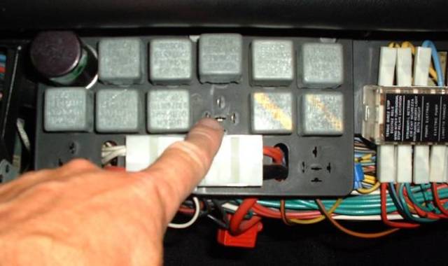 Step 3, Find the high and low beam circuits for the left or right head light. Choose the ones with duplicate male spades on the lower side of the fuse holder. MOVE the existing connectors to the rear set of spades.  Step 6, Pop the blue wires from the 3 and 6 o'clock positions on the 'motor' relay base. 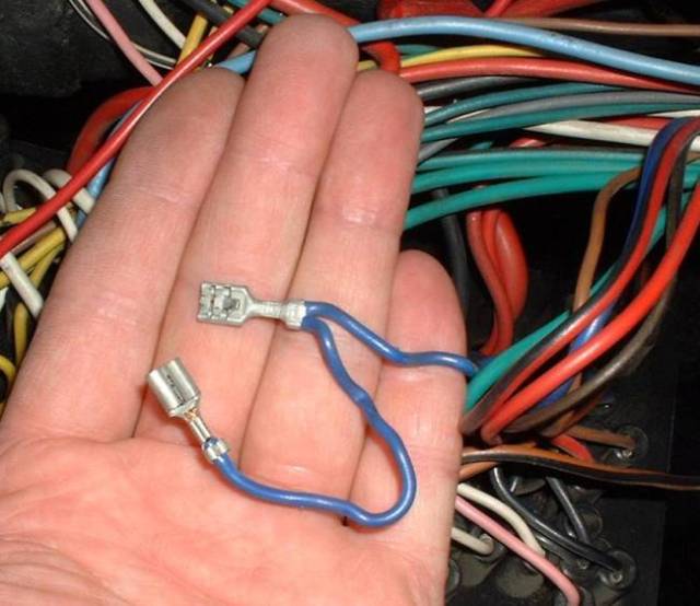 Step 7, Cut the 6 o'clock wire from the 3 o'clock terminal. 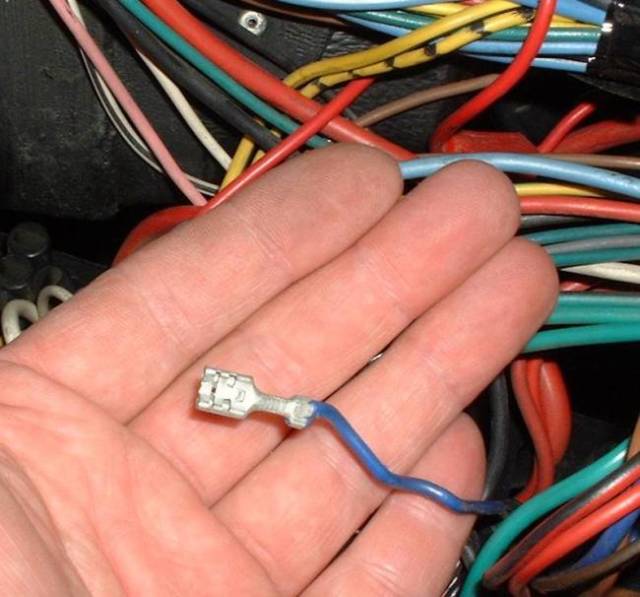 Step 9, Make up the new harness and install to the fuse block at the two open spades for the head light circuits. 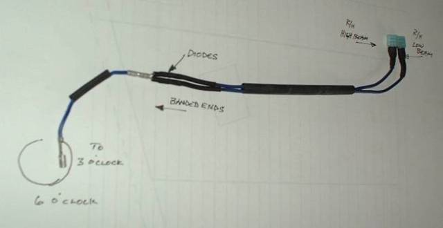 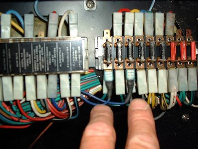 Install the remaining end of the harness into the 3 o'clock position of the relay base. 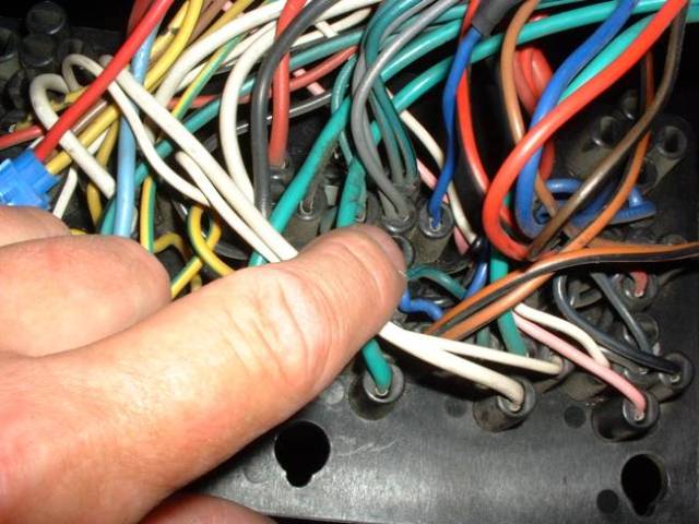 Viola! DJ |